Decimal and binary both use a positional numbering system
Base ten: first position is \(10^0\), then \(10_1\), \(10_2\), etc
Base two (binary): first position is \(2^0\), then \(2^1 = 2\), then \(2^2 = 4\), etc.
Unsigned Binaries
Regular binary doesn't incorporate a sign anywhere, but thus cannot represent negative numbers
Largest number in \(k\) bits is \(2^k - 1\) and would be \(111\dots1\), \(k\) times
Decimal to Binary Conversion
Method of repeated division: Take a decimal number. If the number is odd, add a \(1\) to the list and subtract \(1\) from the number. Otherwise, write a \(0\). Then, on the line below, divide the number in half and keep doing the same thing. The binary representation of the number is read bottom to top
Method of repeated subtraction: find the largest power of two that the number is larger than, subtract that, and at a 1 at the corresponding place in the binary number. Keep repeating this process until arriving at \(0\)
2-Complement Notation
Convention: \(-1 = 111\dots1\)
Leading \(1\) indicates a negative number
Leading \(0\) indicates a positive number
Conversion to negative number: flip the bits and add 1
\(x + \bar{x} = -1 \implies -x = \bar{x} + 1\)
Largest positive number with \(k\) bits: \(011\dots1 = 2^{k-1}-1\)
Smallest negative number with \(k\) bits: \(1\dots11 = -2^{k-1}\)
Sign Extension
If more bits are allocated for a number, we must make sure that the number has the same value by sign-extending it
Positive numbers are sign-extended with \(0\)s, negative numbers are sign-extended with \(1\)s
Adding leading \(0\)s for positive numbers and \(1\)s for negative numbers doesn't change their values
Sign-extension in RISC-V
RISC-V words have 32 bits
If a 12 or 20 bit value needs to be stored, it should be sign-extended
Example: addi t0 t0 15
addi meaning "add immediate"
The immediate takes up 12 bits in the instruction, but is sign-extended to 32-bits for the computation
V02 - Storing Data in Memory
Hexadecimal Notation
Binary numbers can have digits grouped into 4s and be expressed as hexadecimal numbers
Prefixed with 0x to let us know they are hexadecimal
With two's-complement, negative numbers usually have leading Fs
Memory
Each byte stored in memory has an index called an address
E.g. 0x00001004 is an address
On a 32-bit machine, addresses have 32 bits
Each address points to a value
Special named addresses are called registers
Memory Organization
Each memory address points to a single byte
Since memory addresses measured in bytes, each consecutive memory address differs by 4 bytes
Each individual value in memory is a byte, but these are usually clumped into groups of 4 to form a word
Memory can only be accessed at word-aligned addresses; offsets must be used to access individual bytes
Endianness
RISC-V is little-endian: the first bit in the number is the most significant bit (the one that represents the highest power of two)
The 1's bit is the last (rightmost) bit in the number
The least significant bit is stored at the smallest memory address
Advantage: memory slices read like place-value notation numbers
Big-endian architectures do the reverse
There is no "right choice"; they are equally right
V03 - Organization of a computer
Arithmetic Operations
# Arithmetic Add
add a, b, c     # a <- b + c

# Add immediate
addi a, b, 20   # a <- b + 20
Compiling C Code
// C code to compilef =(g+h)-(i+j)// RISC-V Implementationadd t0, g, hadd t1, i, jsub f, t0, t1// Assumptionsf goes in s0, g in s1, h in s2, i in s3, j in s4
Note that each "temporary" value in the c assignment is calculated, and those are used to calculate the final value
This is what registers t0 to t6 are for
Register Types
RISC-V has a 32x32 bit register file; it has 32 registers: x0 to x31
These have the following aliases
t0 - t6 for temporary values
s0 - s11 for saved variables
Addressing an Array
If the array \(A\) contains values of size \(n\) bytes, then we access \(A[i]\) in memory at \(\text{firstElementAddress} + (n*i)\)
In practice, we often need to calculate the offset for this address using arithmetic instructions, save it in a register, and then use that register to access the memory we want
// C codeA[0]= h + A[2]// RISC-V Implementationlw t0,8(s1)// loads A[2] by using an 8-byte (2-word) offsetadd t0, s2, t0 // adds the two terms togethersw t0,0(s1)// saves the result where we need it (0-word offset)// Assumptions: h in s2, A in s1
lw t0, 8(s1)       # takes the value in the memory address s1 with offset
                   # 8 and saves it in t0
sw t0, 0(s1)       # saves the value in t0 at the memory address s1 with offset 0
The offset describes how many bytes forward in memory the memory address should be loaded at (notation: n(register))
This number can be negative
Registers vs. Memory
Registers are faster to access than memory
Using memory requires loads and stores; registers do not
We aim to use only the registers if we can
Memory should be used for composite data, i.e. arrays, strings, structures, etc.
Immediate Operands
An immediate is a number specified directly in an assembly instruction
E.g. addi t0, t0, 1 has the immediate \(1\)
These exist to make the common case fast (a design principle of RISC-V): small constants are often required. No need to load these out of memory all the time
V04 - Data Transfer between Memory and Registers
Example: lw (load word)
Example: sw (save word)
V05 - Binary Representation of Instructions
Instructions get encoded into binary numbers
This is called machine code
RISC-V, being 32-bit, compiles into 32-bit instruction words
General Idea
Different segments (bit fields) of the word store different things, including
The addresses of the registers involved
The operation being done (opcode and funct codes)
Immediates
Different bit fields may encode things differently
E.g. registers can't be negative, so their encoding is not two's-complement
There are a bunch of different formats that are optimized for different kinds of things
Bits might not be directly in order; there are hardware
Formats
V05 - Branches and Jumps
In code, we need to make decisions: if this, then that
// C codeif(i == j){ f = g + h;}else{ f = g - h;}// RISC-V Implementation bne s3, s4, Subtract // branch to subtract if s3 does not equal s4 add s0, s1, s2 // add statement jal zero, Exit // jump to exit (jal zero always jumps)Subtract: sub, s0, s1, s2 // subtract statementExit:...
New instructions and registers
bne: Branch if not equal
There's also bge (branch \(\geq\)), blt (branch \(<\)), and beq (branch \(=\))
The other two inequalities aren't necessary, since we can accomplish those with what we already have (design principle at work)
jal: Jump and Link
If first register is x0, it is an unconditional jump (j can just be used in RARS are a shortcut for this)
It is really about jumping to functions; jal automatically writes the return address (next instruction after the jal) into the corresponding register
x0: register that is hardwired to the constant 0 and won't be overwritten
Useful for setting one register to another (mv in RARS is really add t0, t1, zero), setting a variable to \(0\), and jumping
Branch instructions use the SB type
The label to branch to (actually a line number after assembly) is stored as an immediate
This instruction leaves more spaces for the immediate so the jump can be as far as possible
Jumps use the UJ (unconditional jump) type, which leaves even more space for the immediate
V06 and V07 - Logical Operations and Large Constants
Shifts
slli: Shift Left Logical Immediate: shifts bits left and appends 0s to the little end
E.g. slli, t2, s0, 4 with \(t_0 = 00000010\) would set \(s_0\) to \(00100000\)
Shifting left by \(n\) bits is equivalent to multiplying the number by \(2^n\), and is much faster
Shifting left by \(16\) moves the first half of the word into the second half
Shifting left by \(32\) makes the register equal to \(0\)
sll: non-immediate version of slli
srli: Shift Right Logical Immediate: shifts bits right and appends 0s to the big end
E.g. srli, t2, s0, 2 with \(t_0 = 01000000\) would set \(s_0\) to \(00010000\)
Shifting right by \(n\) bits is equivalent to floor-dividing by \(2^n\), i.e. \(f(r_0) = \displaystyle\lfloor{\frac{r_0}{2^n}}\rfloor\)
Floor division because the least significant bits get lost
srli is not sign-extended
srl: non-immediate version of srli
srai/sra: Shift Right Arithmetic (Immediate): these sign-extend the right-shift
Bitwise Operations
add t0, t1, t2
or t0, t1, t2
xor t0, t1, t2
Each regular logical operation, performed bitwise (comparing each bit together with its correspondent in the other number)
Each of these have an immediate version (at "i" to the end of the instruction)
Bitmasks
The andi instruction can be used to implement masking since it only gives back the bits that are \(1\) in the immediate
E.g. using \(00001111\) gives the first four bits of whatever the other value is
The bits where \(1\) are in the immediate are unchanged; the rest are \(0\)
Getting a Specific part of a Number
To get some specific bits from a number, there are two strategies
Number is small
Figure out the immediate you need that is \(1\) for the bits you want and \(0\)
Use andi to mask for those bits
Shift the result to the right using srli
Number is large:
Figure out the immediate you need that has the right pattern of bits
Shift it to the left
Mask and shift the result to the right like before
Both of these can also be accomplished by only shifting
Shift in both directions up to each end of the bit field you want; the rest of the number gets filled with 0s
xori ... -1
Using xori with the \(-1\) immediate performs logical negation (flips all the bits)
This is because the two's-complement of \(-1\) is \(111\dots111\), and xor flips these
Loading Immediates
li: loads an immediate into a register, starting at the little (least significant) end
This is a RARS pseudo-instruction, not a real one
RARS implements this as follows
# target
li s0, 0x0FFFF000

# implementation
lui s0, 0x1000
addi s0, s0, -256     # -256 is 0xF00, with addi's sign extension 0xFFFFFF00
# adding these forces everything left of the 1 to roll over to 0 (amazing!)
lui: loads an immediate into a register, starting at the most significant end
Essentially equivalent to using li to load it, then shifting it to the left by the remaining amount so that the loaded value reaches the most significant end
This is a real instruction
Bits that aren't used by LUI get zeroed; no original bits remain after an lui instructions
Example for Masking, Large Constants
Topic V0A is an example where actual RISC-V instruction binary representations are compared to learn more about what they do. This involves
Bitwise logic
Moving groups of bits around in the word
RISC-V instruction type knowledge
Manipulating large constants
V08 - Loops and Conditionals
While Loop
// C Codewhile(save[i]== k){ i = i + j}
Idea: keep evaluating the loop condition, branch to the top of the loop if it's true and branch past the loop once it's not
In particular, the most efficient order is
On startup, immediately perform actions required to evaluate condition and evaluate
Branch to exit if true, continue if false
Perform loop body, including iteration
Perform actions required to evaluate condition and evaluate. Branch back to loop body if false, continue if true
        bne ... , Exit   # check condition immediately
Loop:   ...              # start the loop body here (on this line)
        add ...          # (cont. ) loop body and iteration
        beq ..., Loop    # jump to loop top or continue if fulfilled
Exit:
to add: look in slides and figure out what the less efficient example is (the "first thought" example)
More Conditional Operations
slt: set less than (sets 1 if less than and 0 otherwise)
slti: set less than, with immediate
Are used in conjunction with beq, ..., zero, Label for inequality based loops
beqz, bnez are pseudo-instructions in RARS
sltu, sltiu are the unsigned versions of slt and slti
We only need this one because we can reverse comparison order and use beq ... zero for other conditions
Basic Blocks
A basic block is a sequence of instructions with no branch targets (except the beginning) and no branches (except at the end)
Thus, if one instruction in the block is evaluated they all will be or have been
Compilers identify basic blocks for optimization
V09 - Storing Arrays in Memory
An array is a contiguous chunk of memory
Arrays of integers have one word per element, since integers are 32-bit
Strings (arrays of characters) have one byte per element, since ASCII characters are 8-bit
Strings also get null-terminated; their last character is \0 = 0x00
![[V03 - Organization of a computer#Addressing an Array]]
Another C Example
# C Codey = A[B[j]]# RISC-V Implementationslli t1, t0,2// 4 * jadd t2, s7, t1 // B + 4 * j (address of B[j])lw t3,0(t2)// store B[j] in t3slli t4, t3,2// 4 * B[j]add t5, s6, t4 // A + 4 * B[j] (address of A[B[j]])lw s3,0(t5)// load the thing at this address into y
V0B - Procedure Calls, Stack, and Memory Layout
A callable unit has many names: procedure, function (no side effects), routine, subroutine, subprogram, method (object-oriented), etc.
We will use the term procedure
Procedures
A procedure is a "function" with side effects
The caller is the code that references the function
E.g. foo()
The callee is the code that defines the function, and runs when the function is called
E.g. void foo() { ... }
Functions can call other functions; this is what makes them so useful as tools of abstraction
Returning
Functions must return program flow to the point where they were originally called
The function returns to the return address
The caller must remember the return address while the function is running
The callee must return to the correct address
RISC-V has a single register ra to store a return address
It may also have return values: values the function computes that the caller likely wants
The Stack
Since RISC-V only has one ra register, we can't just put it in there because functions returned by other functions would have their return addresses overwritten
The stack exists in memory, and stores the following, which form a stack frame
The value of fp (the frame pointer)
The value of ra (the return address)
Any register modified by the function
Local variables that get stored in memory
The stack pointer in register sp always points to the top of the stack
We use this to figure out where to place the next stack frame
It gets decremented when we write something to the stack
The frame pointer in register fp (s0) points to the start of the current frame
We use this to figure out where to access values in the current stack frame, since this doesn't change relative to existing values if new ones are added
The function is responsible for keeping track of this
What Does the Stack Do when We Call a Procedure?
Address of current instruction (the program counterpc) is written into ra
ra is saved onto the stack, and sp is decremented/updated so it points to the top of the stack
The function is evaluated. Say this includes calling another function
fp is moved up, since this new function creates a new frame. However, if this function doesn't in turn call more, it will stay empty
ra is overwritten with new value and the pc is moved to the new function
The function returns; pc is moved to the value of ra and execution continues as before.
ra is restored from the stack. If we changed other things, they would be as well
The (outer) function returns, meaning
pc is moved to ra
sp is incremented/updated; the function's frame is popped from the stack
(if this is also in a function) ra is restored to its previous value from the stack
Memory Layout
The stack grows downwards from the dynamic memory (i.e. it starts at the highest memory and gets lower) and serves as the automatic storage
The stack (obviously) is a type of stack data structure
The Dynamic data / heap grows upwards from the dynamic memory. This is memory allocated dynamically, like using malloc in C or new in Java
Static data are global variables, constant arrays, strings, etc. These are immutable
Text is the actual program code, stored as binary instructions
V0C - Register Calling Conventions
Different registers are used for different things
There needs to be agreement between the caller and callee about which registers should be used for what purposes, since some are globally accessible and may be overwritten
What values are expected to stay the same before and after a function call?
Running a process is almost like having external code running
Registers with Conventions
s0-s11 are the saved registers: any values from s0 to s11 must remain the same before and after function execution
The callee can overwrite s0-s11 for their own purposes, but must restore them before the function returns
s0 is the frame pointer
t0-t6 are the temporary registers: these are allowed to change after function execution
They should be used as needed for computing things, not relied upon to save values
The callee is free to modify these
a0-a7, ra are the "procedure registers": they are used for things related to procedure calls
a0 and a1 are used to specify parameters for a procedure, and may contain return values from the callee once the procedure is done
a2-a7 are more registers to specify parameters
ra is the return address, and is used to return to the point after the call
sp: The callee must save it - no??
Same as the s registers.
Other Registers
zero: always contains the value \(0\)
sp: stack pointer
gp: global pointer
tp: thread pointer
The frame pointer fp is actually s0
Table of Calling Conventions
Register
Name
Use
Saver
x0
zero
The constant value 0
N.A.
x1
ra
Return address
Caller
x2
sp
Stack pointer
Callee
x3
gp
Global pointer
--
x4
tp
Thread pointer
--
x5-x7
t0-t2
Temporaries
Caller
x8
s0/fp
Saved register/frame pointer
Callee
x9
s1
Saved register
Callee
x10-x11
a0-a1
Function arguments/return values
Caller
x12-x17
a2-a7
Function arguments
Caller
x18-x27
s2-s11
Saved registers
Callee
x28-x31
t3-t6
Temporaries
Caller
V0D - Recursive Functions
Non-leaf procedures are procedures that call other procedures
For nested calls, these need to save ra and callee-saved registers onto the stack and restore them before returning
Recursive functions are non-leaf functions that call themselves
Recursive functions must use the stack, just like any other nested function
It's possible for compilers to optimize tail recursion by simply replacing stack frames instead of pushing new ones, since the stack unwinds immediately when the the base case is reached
Like any function call, recursive function calls add a frame to the stack. If the function is tail-recursive, it is possible that the compiler can optimize the stack use by writing the new values for scoped variables to the same stack frame instead of to a new one each time.
Lecture V0D has an in-depth example of the RISC-V implementation of a recursive C function, which should be consulted as an example
V0E - Different Sizes of Data
Strings are arrays of characters, which are only one byte each. As such, they are typically manipulated on the byte level, not the word level
# load byte from the address in rs1 into rd
# this is sign-extended to 32-bits (fills the whole word)
lb rd, offset(rs1)

# load unsigned byte (zero extension instead of sign-extension)
lbu rd, offset(rs1)

# stores the rightmost byte in rs2 into the memory address in rs1
sb rs2, offset(rs1)
Analogous instructions exist for half-words, which are 2 bytes (16 bits)
These are lh, lhu, and sh
Manipulating Different Sizes of Arrays
When accessing arrays, the number of bytes to increment by is the size of the data being stored
Integer: 32 bits = 4 bytes = 1 word
Character: 8 bites = 1 byte = 1/4 word
Structs: the size of the struct is the total of the number of bytes in each member
String Manipulation Example
An example of the RISC-V implementation of the strcpy function in C is given in Lecture V0E
V0F - Relative Performance
The algorithm determines how many operations get executed
The programming language / compiler / architecture determines how many machine instructions are executed per operation
The processor and memory system determine how fast instructions are executed
The I/O system, including the OS determine how fast I/O operations are executed
Response Time vs. Throughput
Response time: how long it takes to do a task (also known as latency)
Throughput: the total amount of work done per unit time
E.g. multiple processors have the same response time but higher throughput
Power increases over time, but eventually hits a ceiling
Uniprocessor performance is constrained by power, instruction-level parallelism, memory latency
MIPS performance metric: millions of instructions per second
Doesn't account for differences in ISAs between computers and instruction complexity
Execution time is a better performance measure, since that's what ultimately matters
Instruction-level parallelism: hardware executes multiple instructions at once
This is abstracted away from the programmer
Multicore processors: processors with multiple cores. Requires the programmer to execute parallelism themselves
SPEC
SPEC: standard performance evaluation corporation
Has various work groups for systems, high performance, graphics, research
Joint effort between large tech companies in industry and research universities
Develops benchmarks, i.e. programs used to measure performance
Amdahl's Law
Improving a single aspect of a computer doesn't lead to a proportional increase in overall performance
Each aspect only affects the performance a bit, so only that part gets improved proportionally
E.g. doubling the speed of the mul instruction where it accounts for \(50\%\) of the program's runtime can improve the program up to \(50\%\)
Takeaways
Performance and cost is improving due to technological development
Hardware and software development involves hierarchical layers of abstraction
ISA is the interface between hardware and software
Power is a limiting factor; thus, parallelism can improve performance significantly
V13 - Bubble Sort RISC-V Example
Swap Function
Swaps an element in an array with the next element in the array
// Cvoid swap(int A[],int k){int temp; temp = A[k]; A[k]= A[k+1]; A[k+1]= temp;}// RISC-Vswap: slli t1, a1,2// A[] is in a0; get k*4 add t1, a0, t1 // get the address of A[k] lw t0,0(t1)// temp storage for A[k] lw t2,4(t1)// load A[k+1] into t2 sw t2,0(t1)// put A[k+1] into A[k] sw t0,4(t1)// put A[k] value (stored in temp) into A[k+1] jalr zero, ra,0// end function
The V13 slides have an excellent example of generating RISC-V from C for the swap function
Bubble Sort
void bubblesort(int A[],int n){int i, j;for(int i =0; i < n; i++){for(int j = i-1, j >=0&& A[j]> A[j+1]; j--){ swap(A, j);}}}
We move through the list \(n\) times and swap each successive pair of elements that's not in order (\(O(n^2)\))
Implementing Bubblesort in RISC-V
We must remember to follow the for loop template: initialize, then test → loop body → increment, then back to test; branch past loop if test passes
We must remember to save certain values (like \(A[\,]\) and \(n\))
A good exercise to do on one's own to practice transcribing algorithms
Effect of the Compiler
We notice that the compiler greatly speeds up bubble sort, i.e. the relative performance of unoptimized bubblesort vs. optimized bubblesort is high
However, algorithms like quicksort outperform bubblesort considerably, even without any compiler optimization
Takeaway: nothing can fix a dumb algorithm
V14 - Calling Conventions for Functions inside Loops
We have to keep in mind which variables might be altered (temporaries, arguments/returns) and which must stay the same (saved, ra)
We also have to remember to restore saved variables ourselves using the stack
Why is Calling a Function inside of a Loop Different?
It's not!
It's just that since the function gets called over and over since it's inside the loop, the consequences of our poor choices will very likely have an effect
Common antipatterns
Using a temporary value as loop iterator. The function called may change this value; it must be a persistent value
Using the argument registers with respect to the function we are writing the loop in, not the one that we called
V15 - Indexing vs. Pointers
Array Indexing: we keep track of the index of the element in the array we are tracking
We might have to calculate the actual pointer to the element each time
Requires a shift (by \(2\)) inside the loop since we have to multiply the iterator by \(4\) each time, assuming the array is of integers
Pointer Indexing: we keep track of a pointer that moves along each element of the array
We might have a more complicated check to see if the loop is done, since that is usually specified in terms of index
Example: clear writes \(0\)s into every element in an integer array
// Array indexingvoid clear(int A[],int n){int i;for(i =0; i < size; i++){ A[i]=0;// notice we access a value by its array index}}// Pointer Indexingvoid clear(int* A,int n){int* p;for(p =&array[0]; p <&array[size], p +=1){*p =0// notice we deference the pointer to access the value to change}}
The RISC-V implementations are straightforward; they are found in the lecture slides.
We find that the CPI of the pointer indexing method is generally faster, namely because we to iterate and calculate the pointer for array indexing, but both are done in one instruction with pointer indexing
However, the compiler can optimize this difference away when we write in C
Overall, it's better to write whatever makes the code clearer and safer, i.e. with array indexing
V16 - Meaning of Dereferencing
What does *p mean?
In this example, p and x are function arguments, so they correspond to the a0 and a1 registers
void foo(int*p,int x){*p = x;// STORE the VALUE of x in the memory location whose ADDRESS is in p// Analogous RISC-V Instruction: sw a1, 0(a0) (like doing save word) x =*p;// LOAD into x the VALUE from the memory location whose ADDRESS is in p and // Analogous RISC-V Instruction: lw a1, 0(a0) (like doing load word)}
If p and x are in a stack frame, the RISC-V instructions are a bit different
We have to load both p and x into registers (since they are in stack memory), then perform the save word
Remember: to access these variables from the stack, we need to use offsets from the stack or frame pointer
V17 - Examples of String Functions
Strings are stored as arrays of \(8\)-bit characters in memory
These are encoded into integers using the ASCII encodings
Examples of String Functions
All of these are straightforward implementations in RISC-V, and should be done as exercises
strlen: returning the number of characters in a string
Uses are simple for loop that branches if the current character being examined is the null terminator
maxlen: given an array of strings, return the number of characters in the longest one
Requires a nested for loop
Since this a nested array, we have double pointers: pointers to pointers to characters. Note that we will have to perform load instructions twice to achieve this
Uses a function call to strlen
summax: list of classes (which are lists of students): sum of longest names in each session
Once again, requires calling maxlen in a loop
Takeaway: using a lw takes us to the next level closer to the base value
Types
char: character
char* address of or pointer to a char
char**: address of or pointer to a pointer to a char
V18 - Parameter Passing by Value and Reference
What's the Difference?
When passing by value, a parameter must be copied into the stack (or a register) when a function is called
This is fine for small things like integers, but does NOT need to be done for large structures like arrays, structs, etc
Instead, when passing by reference, a reference to the object is passed into the function instead, which means is doesn't need to be copied
This saves space, but means that any changes made to the referenced object will persist after the function is done (mutability and global state)
This can be a good thing (take that functional programmers!) but can also lead to unintended bugs that are difficult to track down
V19 - Synchronization
Naive Approach to Multiple Processors Asking Same Data
Write into a shared place when accessing a resource; when a resource is about to be used, write a \(1\) into it, then proceed
Won't work: nothing is being checked
Check before writing too. Only write if the shared place is a \(0\)
This seems like it would work, but it's possible that P1 reads, then P2 reads, then P1 writes, then P2 writes. Basically, since there is a small period of time between reading an writing, if P1 and P2 try to check at almost the same time, they might both read, then both write a \(1\) without realizing they are overwriting. This leads to a data race
Data race: the result of a read from memory depends on the order of access
This is what synchronization tries to avoid
Synchronization
Requires hardware support and an atomic read/write operation
I.e. there is a specific instruction in the instruction set that corresponds to synchronous access of data
This instruction could be an atomic swap of register and memory
Atomic read/write memory operation: an operation that performs a read and write at exactly the same time; in a single operation
No access to the location is allowed between the read and the write operation
This avoids the data race problem from the naive implementation
Synchronization in RISC-V
Load reserved: used to load a shared resource, like whatever signals if the memory is free to access
lr.w, lr.h, lr.b, etc.
Store conditional: succeeds if (what is stored in) the location has not changed since the load reserved; fails if the location has changed
Returns 0 in rd if the store succeeds
Returns non-0 in rd if the store fails
Atomic Swap Example
try:// s1 contains the shared resrouce between the processorslr.w t0,(s1)// load reserved word from the shared resource// t0 contains the value in s1// now that a thing has been loaded from the synchronized area// every processor (involved?) has a record that the address of s1 is load-reservedsc.w t1, s4,(s1)// store conditional into s4 (?) from s1 (shared area)// t1 now contains the status of the store operation// now the address is no-longer load-reserved;// the address of s1 is no longer stored as load-reserved if it succeededbne t1, zero, try // if the store fails, branch back to the try// we know the synchronized thing succeededadd s4, zero, t0 // put the loaded value into s4
Detailed slides for this example are found in the V19 Slides
V1A and V1B - Blackboard Architecture and Transactional Memory
Based on how people work at a blackboard: people don't communicate with each other directly; they write everything they need to solve a problem on the blackboard where everyone can see it at the same time. If a person has a better solution, they simply erase what they want to replace on the blackboard and write that. No ambiguity exists here because it is plainly visible when someone is writing on the board.
Blackboard Architecture
Example: Newton's Method
Two processors are trying to find the minimum (or get as close) as they can
One is using newton's method; the other is guessing randomly
If one has a better guess than what is currently on the blackboard, it will replace the guess
The newton's method process also has to read the blackboard to know where to check the next derivative
Both the current min's x-value \(x\) and y-value \(f(x)\) are on the board
No-lock Version
Everyone writes to the shared blackboard to solve their problem
However, they just read and write randomly, so a value might get overwritten while another processor is using it in a calculation, and the process won't "realize" this has happened
E.g. a processor writes the value for \(x\), but before it writes \(f(x)\), the other one reads that \(x\) value and \(f(x)\) value, getting an inconsistent pair
In order to solve this, a lock is required
Lock Version
Lock: a variable that is \(0\) when no one is writing to the blackboard and \(1\) when someone is accessing the board (reading or writing)
The lock is read and written to using load reserved and store conditional
Reads and writes are only allowed by a new processor when the lock is \(0\)
Before writing to the blackboard, the store conditional instruction is used to update the lock variable to \(1\) to let everyone looking at the blackboard know that it is being accessed
Blackboard Architecture Terms
Critical section: the shared resource
Race Condition: when a resource is being accessed by multiple processes at the same time
Starvation: one process fails to access a resource for an extended amount of time
Deadlock: no progress
Transactional Memory
Architectural support for lock free data structures
Implemented on mainframes
Each thread in a transaction can perform an LL on many different memory locations and the commit operation performs a kind of SC that takes effect on those multiple locations simultaneously, with either every store failing or succeeding together
Leads to vulnerabilities
V1C - Compiling, Linking, and Loading
Producing an Object Module
Assembler and/or compiler: Translates the program into machine instructions and provides information for building a complete program from the pieces
Header: describes the content of the object module (function definitions, etc)
Text Segment: translated instructions
Static Data Segment: data allocated for the entire life of the program (e.g. "external" files that the program uses but doesn't modify)
Relocation info: for content that depends on the absolute address of where the program is located
Symbol table: global definitions and external references
Debug info: for associating with the source code
Linking Object Modules
Produces an executable image
Merges different segments
Figures out the addresses of the labels
Figure out the paths of the local and external references (relative and absolute paths)
Program can be loaded into an absolute location in virtual memory, so location dependencies don't need to be fixed (???)
Loading a Program
Load the image file on the disk into the memory
Read the header to figure out the segment sizes
Create virtual address space
Copy text and initialized data into memory
Or set up page table entries so they can be included from there
Set up arguments on the stack
Initialize registers, including the stack pointer, frame pointer, gp
Jump to the startup routine (copies the arguments into a0, etc. and calls main, then invokes the exist system call when main returns)
Dynamic Linking
Only link and load a library procedure when it is called
Requires the code to be relocatable: the linker has to fix the code to run in a new location
Position-independant code can run anywhere in memory without needing to be changed
Avoids image bloat and automatically adapts to new library versions
Lazy Linkage
watch video!
Dynamic JIT Compilers
V1D - Computer Arithmetic
Operations on Integers
Addition and subtraction
Multiplication and division
Dealing with overflow
Addition
Bitwise Addition
Two bits get added
There is a carry bit to signify if the one bit has overflowed
Cin: carry in: input for the carry bit
Cout: carry out: output for carry bit (whether it gets used)
Four possible results of this are indicated below, as well as the logical circuit used to execute the arithmetic
Collectively, this structure is known as a half-adder
The xor operation happens to encapsulate most of the logic for addition; however, in the case that both digits are 1, we also need a carry bit keep track of the next place
Combining Half-adders
Two half-adders can be combined into a full one-bit adder, which address three bits
These correspond to \(a\), \(b\), and \(Cin\)
Outputs: the sum \(S\) (a one-bit number, i.e. \(0\) or \(1\)) and \(Cout\) (whether a carry is used)
We can abstract this whole circuit as a black box that adds two one-bit numbers
It has a truth table like any other combinational circuit
Ripple-carry Adder
We take a full adder and connect the carry-out of the first adder into the carry-in of the second adder, then do the same with the next, etc
If we connect \(n\) adders this way, we can add together two \(n\)-bit numbers
It is indeed that easy!
However, travelling through a circuit takes time; the ripple-carry adder is \(O(n)\), where \(n\) is the number of bits in the number
This is less efficient than it can be; we can use a carry look-ahead adder
Carry Look-ahead Adder
Carry look-ahead unit: computes the propagate signal and lookahead signal
Is itself a black box that can be implemented logically
Each full adder has a propagate bit and a generate bit
Propagate bit: tells you that if the unit receives a \(Cin\), then it will propagate that carry to the next unit
Generate bit: regardless of the \(Cin\) state, this unit will generate a \(Cout\) of \(1\)
Each adder unit has its \(S\), \(p\) (propagate), and \(g\) (generate) bits feeding into the carry lookahead unit
Receives its \(Cin\) from the carry lookahead unit as well
Each carry lookahead unit has a final \(Cout\), \(p\), and \(g\), which means they can be chained together as well
Logic for generating the \(g\) and \(p\) signals
\(g_i = A_i \cdot B_i\)
\(p_i = A_i + B_i\)
This is more efficient because having a central source know the generate and propagate properties will allow it to "figure out" if it can skip certain parts of the calculation, since it already knows the answer
E.g. if all the generate bits are \(1\), whatever \(Cin\) to the main unit is will be the \(Cout\) of t
Subtraction
Add the negation of the second operand
The negation in this case will be two's-complement negation, not logical negation
Subtraction can underflow, much like addition overflows
Overflow
If the sum is too large for the bits containing it, then the sum will overflow and the sign of the result will change
E.g. in \(4\) bits, \(7\) + \(1\) is \(-8\) (assuming two's-complement representation)
If inputs have different signs, there is no chance of overflow. However, in the other cases, overflow is possible
This is the opposite for subtraction
Checking for Overflow
Unsigned addition: if either of the operands is smaller than the result, an overflow occurred
Also works for a signed addition with one operand signed known (likely an immediate)
Signed addition: compute \(c = a+b\) into new register, check if \(c < 0\) and if \(a < b\). If one of these is false and one is true, then an overflow occurred
This needs to done manually in RISC-V
Design Principles: Dealing With Overflow
Some languages, like C, RISC-V, etc ignore overflow; they give you enough rope to hang yourself with
RISC-V has no special instructions that help you perform overflow checks
Instructions that could result in overflow should be used with a check
Then, if an overflow occurs, invoke the exception handler
Other languages require that an exception is raised when an overflow occurs
Save PC in user exception program counter
Jump to handler address which is stored in user trap handler base address
Multimedia applications involve different data sizes (e.g. \(8\) and \(16\)-bit numbers), so there are more efficient arithmetic instructions to help with that
V1E - Multiplication and Division
Unsigned Multiplication
For \(a\times b = c\), \(a\) is the multiplicand, \(b\) is the multiplier, and \(c\) is the product
The length of the product is the sum of the operand lengths
E.g. a \(4\)-bit number times \(4\) bit number is an \(8\)-bit number
Multiplication Hardware
Multiplicand, multiplier, and product (after computation, 0 initially) will be stored somewhere
Only the bottom half of the multiplicand register is used to hold it; the multiplicand shifts left, so the place it is stored needs to be twice as big as the multiplicand itself
64-bit adder (ALU) to perform addition operations
Control unit that performs tests to decide what calculations to do
Multiplication Algorithm
Calculate a bunch of partial products and add them together, like the elementary school multiplication algorithm
The sum terms are the individual bits of the multiplier times the multiplicand
Since these are binary, multiplying by \(1\) or \(0\) is the same as either adding the number or not
We have to shift left (multiply by 2) each time we add a term, since we need to move to the next place-value place
Multiplicand shifts left and multiplier shifts right
Thus, we need to start with the most significant bit of the multiplier and end with the least significant
Full Run-through of a Multiplication
The least significant bit of the multiplier is checked. If it is
1: Multiplicand is added to product (using bitwise addition)
0: The addition step is skipped and we move back around to the shift step
Multiplicand register shifts by one bit to the left
Multiplier shifts to the right by one bit
Better Multiplication
Notice
The upper half of the multiplicand doesn't get used; it gets initialized to \(0\)s and then shifted out of the register during the multiplication
The adder can only write into the upper half of the product, then shift to the right
Thus, we can store the multiplier in the bottom half of the product register to save space, since we will get rid of that area eventually
Also, the shifts we performed for the separate registers before can be executed with one shift of the combined register
Fastest Multiplication
Idea
We compute all the partial products instead of accumulating them in the product sequentially (this uses more storage but gives us speed)
Then, we use a tree of adders to add each two results pairwise, then the results pairwise, etc.
This is more expensive because it takes more space and more adders, but performs multiplication in \(O(\log{n})\) adds, where \(n\) is the number of bits
Pipelining
Pipelining: performing tasks at staggered times so that every resource is being used to perform the task
As opposed to waiting for the task to be done before starting a new one, which leaves resources dormant if the task is made up of subtasks
For our multiplication algorithm, this means that we don't need to wait for each layer of the tree to be done computing before performing the next multiplication operation
Instead, each layer of the tree may be used for a different operation at the same time
Note that this doesn't make a single multiplication algorithm any faster, but does speed up a sequence of them
RISC-V Multiplication
mul: performs 32x32 multiplication and places the lower 32 bits in rd
Note that we lose half the bits!
mulh: performs 32x32 multiplication and places the higher 32 bits in rd
Together, mul and mulh perform a full multiplication
This is because a 32x32 bit multiplication is 64 bits, which fits into two words, not one
Internally, the RISC-V processor will merge the operations into one operation if it sees these two right after each other
mulhu: performs unsigned multiplication and stores the upper half into the register
mulhsu: performs signed x unsigned multiplication and stores the upper bits
We always use mul for the lower bits; we choose for the upper bits since those are the ones that would change based on the sign (???)
Division
It is possible to do this with multiplication hardware, but we will not explore that
RISC-V
div: performs integer division
Also divu
rem: stores the remainder of an integer division
Also remu
V1F - Polling, Interruptions, Watchdog Pooling
Sometimes, we need to process asynchronous events that can happen at any time, and will cause the program to stop evaluating what it was before, then return to it
E.g. keyboard input
Exceptions and Interrupts
Exception: something caused by executing instructions (e.g. an error, like reading from a misaligned address)
Interruption: something caused by something external to the program (e.g. I/O, power failure)
Exception Overview
When an exception occurs, the processor will
Save the address of the instruction that caused the exception in the User Exception Program Counter (upec)
Jump to a specified address, which is stored in the User Trap Handler base address (utvec). This leads to OS code that can handle the exceptions; this is the OS's responsibility by definition, since RISC-V cannot deal with it
The OS needs to know the following things
The reason for the exception (can be reported in two ways)
Cause register: a special register that encodes the reason (i.e. each type of reason has a number); the OS decode it to find the reason
Interrupt vectors: PC receives a BASE field (the address of the start of the handler (?)
I.e. instead of decoding the exception itself, the PC gets directed to different code directly for different types of exceptions
The utvec mode bit determines which way gets used (\(0\) for cause register, \(1\) for vector)
The particular instruction that called the exception; this will be in uepc
Polling vs. Interrupts
Polling: processor stops regularly and checks if an outside process needs attention
This wastes time and resources, but doesn't require trust that the process will notify the main process when necessary
Common for low-performance or embedded systems because of predictable timing, low hardware cost
Interrupts
The external process sends an interrupt to the main process when it is done; this causes the main process to stop and deal with the external process
Work similarly to exceptions, except it is not synchronized to the program's instructions
Polling Watchdog
When there is a cause to interrupt the processor, start a timer
If the processor has not pulled for the input by the time the timer is done, interrupt the processor
This way, the processor has a bit of freedom to poll when it is most convenient for it
Originally proposed for multi-threaded systems
V20 - Exceptions in RISC-V
What Happens when an Exception Occurs
Process jumps to the coding starting at the base of the trap handler (exception handler, stored in utvec)
Exception handler examines the cause of the exception and jumps to the corresponding OS handler for the exception in question
The OS handler may
Terminate the process that caused the exception
Perform an action (e.g. print) and return
Writing an Exception Handler
Can an exception handler write registers on the stack?
MIPS: possibility that the sp itself is corrupted, so no
In RISC-V, there are multiple levels of exception handler, so it depends
User level: maybe, so RISC-V will let you
Supervisor level and above: nope!
As such, we will assume that the stack cannot be used
So where do we store registers? We create a stack in the kernel area
All the registers must remain unchanged before and after an exception
Control and Status Registers
ucause register: encodes the reason that an exception or interrupt was raised
Status register: ustatus
Most important bit: bit 0: depends if user interrupts are enabled or disabled
Interrupt-enable register: uie
Control and Status Register Instructions
Each instruction that manipulates a CSR has 12 bits to specify it
Atomic read-write (read-write in one operation)
csrrw: control status register read-write
csrrw t0,0, t1 // t0 <- CSR0 zero extended AND CSR0 <- t1csrrwi t0,0,0x01// t0 <- CSR0 zero extended AND CSR0 <- imm
csrrc: atomic read and clear bits
csrrc t0,0, t1 // t0 <- CSR zero extended AND CSR <- CSR & /t1// i.e. complement of t1 bitwise anded to CSR// any bit in t1 that's a 1 has to become a 0 in CSR// immediate version also exists
List of Control and Status Registers
Register name
Register number
Usage
ustatus
0
interrupt mask and enable bits
uie
4
Enable user interrupts such as Timer and Keyboard (external)
utvec
5
The base address of the trap handler is stored in this register
uscratch
64
Temporary register to be used freely in the user trap handler
uepc
65
address of instruction that caused exception
ucause
66
exception type
utval
67
memory address at which an offending memory reference occurred
uip
68
User interrupt pending
List of Exception Codes
Interrupt
Exception Code
Description
1
0
User software interrupt
1
1
Supervisor software interrupt
1
2
Reserved for future standard use
1
3
Machine software interrupt
1
4
User timer interrupt
1
5
Supervisor timer interrupt
1
6
Reserved for future standard use
1
7
Machine timer interrupt
1
8
User external interrupt
1
9
Supervisor external interrupt
1
10
Reserved for future standard use
1
11
Machine external interrupt
1
12-15
Reserved for future standard use
1
>=16
Reserved for platform use
Three levels of execution
When the user program is running (the programs that we write)
OS-level
Machine level: software running underneath the operating system (e.g. BIOS)
Re-entrant exception Handlers
When will exceptions be enabled (i.e. can happen again)
I.e. can exception handler code be itself interrupted?
If we want to be able to throw exceptions during exceptions, we need a re-entrant exception handler
So, we need to store some sort of stack somewhere to support this recursive exception behaviour
This is the kernel stack, which is created in the kernel memory reason
The pointer for this stack will be a regular RISC-V register that you designate
In the handler, we must
Write the values to the stack and move the kernel stack pointer as necessary
Restore the position of the pointer before the handler is done
Exceptions must be disabled in between writing to the stack and moving the kernel stack pointer
This is done by updating the value in sscratch, which gets updated with atomic read-write
I/O devices are managed by I/O controller hardware
Transfer data to and from the device
Synchronizes operations with software
Command registers: cause a device to do something; the I/O is bound to the register
Status registers: Indicate what the device is doing and if errors occur
Data registers: writing and reading to/from the device
Types of I/O Mappings
Memory mapped I/O: some special memory addresses are used to access an I/O register
Address decoder captures I/O accesses
What looks like a regular load actually loads data from the device; store commands work the same way
OS assures that I/O-mapped memory is only accessible to the kernel; users cannot interact with them directly
Thus, we use ecalls to access the I/O
I/O instructions: there are a separate set of instructions to access I/O registers
These can only be accessed in kernel mode
Storage and I/O
All the I/O controllers are connected to the I/O interconnect, which communicates with the processor via interrupts
This interconnect is also connected to memory in order to serve memory-mapped I/O
- Parallel bus: multiple data lines (wires)
- Busses are either synchronous (and use a clock signal like a processor) or asynchronous (use some sort of handshake)
V23 - Floating-point representation
Normalization: expressing a number with one digit before the decimal point
Used for scientific notation
E.g. base \(10\): \(26.73 = 2.713_{10} \times 10^1\)
Converting Decimal Numbers to Binary
Direct option: just figure it out. The decimals work the same way as base-\(10\), just with inverse powers of \(2\) instead of \(10\)
Multiplication option: multiply by a power of \(2\), convert, then place the decimal point appropriately
Repeated multiplication: like [[V01 - Binary Representation#Decimal to Binary Conversion|repeated division]], but multiplying by \(2\) instead of dividing by it
Floating-point Standard: IEEE 754 for 32 bits
Standard for single (32-bit) and double (64-bit) precision floating point numbers
Developed in response to diverging representations; now ~ universal
Technical Specification
Bits are allocated as follows
[1]: sign (0 for positive, 1 for negative)
First (most significant) bit of the number
8 bits: biased exponent (unsigned integer)
Displaced by \(-127\)
23 bits: fraction (significand)
Uses inverse powers of two instead of regular ones
First bit (MSB) represents \(1\), second represents \(\frac{1}{2}\), then \(\frac{1}{4}\), etc.
So, the whole fraction ranges between \(0\) and \(2\), which makes sense since it "fills the gap" between each possible step of the exponent value
Specifications with even less bits are useful for machine learning
Various allocations for exponent vs. fraction
As little as 8 bits are sometimes used
V24 - Floating-point Arithmetic
Specific Operations
Addition
Align decimal point of numbers to that of the number with the smallest exponent (leads to a loss of precision)
Add significands
Renormalize the result
Round-off the result to fit the available representation space
Multiplication
Add the exponents together
Multiply the significands
Normalize the product
Round-off the product
Accurate Arithmetic
guard and round digits???
Involves keeping track of a round and guard digit
sticky bit
All these are specified by IEEE 754
Associativity of Floating Point Addition
Floating-point addition is not associative
E.g. \(-1.5_{10} \times 10^{38} + 1.5_{10} \times 10^{38} = 0.0_{10}\), but \(1.5_{10} \times 10^{38} + -1.5_{10} \times 10^{38} = 1.0_{10}\)
Parallel programming may assume associativity when interleaving operations
Such programs need to be validated under varying degrees of parallel-capacity
V25 - Floating Point in RISC-V
video…
Floating point and f-registers
RISC-V supports single-precision and double-precision formats
Has three architecture extensions: F, D, and Q; each add f-registers that can be used like the regular ones, but for floating-point values
F-extension: adds f-registers for \(32\)-bit floating point
Note that f0 is not hardwired with the value \(0\)
D-extension: Widens the f-registers to 64 bits for double-precision floating-point
Q-extension: Widens to 128 bits for… even more precision I guess
Q for "quads"
Floating Point load and store
// floating-point load wordflwrd, imm(rs1)// loads word into an f-register// F[rd] = M[R[rs1] + imm]// rs1 is an f-register// floating point save wordfsw rs2, imm(rs1)// saves into regular memory from an f-register// M[R[rs1] + imm] = F[rs2]// rs2 is an f-register
Floating Point Arithmetic Instructions
Both exist in single-precision (.s) and double-precision (.d) variants
fadd.s // additionfsubs.s // subtractionfmul.s // multiplication fdiv.s // divisionfeq.s, flt.s, fle.s // comparison (rd is set to 0 if values are not equal, etc)fcvt.s.w // converts integer in rs1 to floating-point value, which gets stored in rdfcvt.w.s // same as above, but converts floating-point -> integer
Example
Topic V26 is an example of a floating-point matrix multiplication function translated/compiled from C to RISC-V
It contains a large subset of the operations discussed in this topic
The circuit and "read" from the state and "write" to the state
Also known as a finite state machine
Combinational Elements
AND gate: \(A \land B\)
Multiplexer: has multiple inputs and one output; chooses one input to pipe through to the output
Has a switch that determines which input becomes the output, I.e. \(S \, ? \, input1 : input0\)
Adder: \(Y = A+B\) (discussed earlier)
ALU: \(Y = F(A, B)\) for some operation \(F\)
Sequential Elements
Register: stores data in a circuit
Uses a clock signal to determine when to update the stored value
So, inputs are clock signal (Clk), data input (D), and output (Q, current state)
At every clock transition (change in value), the input will be stored and become the output (this means it is edge triggered, triggered when the clock moves from \(0\) to \(1\))
However, this means all the registers change every clock signal, which is not useful
Register with write control: only updates on the clock edge when the write control is 1 (additional input to the register)
Requires an additional input: Write signal
The output only updates to match the input when the Write signal is true
Clocking Methodology
Combinational logic transforms the data during clock cycles
In between clock edges
Inputs data from state element and outputs the transformed data to state element
This may be different elements or the same element
Longest delay determines the clock period
Building a Datapath
Datapath: processes data and addresses in the CPU (i.e. takes care of the instructions and their accesses to ALU and memory)
Must include
Program counter (remember, this is the address to fetch the current instruction being executed from memory)
Memory (clearly we need this to get the instructions)
ALU for operations that don't read/write (at least, we need an adder to increment the program counter)
ALU Operation input to specify which operation we are performing
Regular two inputs, one output scheme
Register file
Register File
Register file: combination of all the registers in the processor
Inputs are a 5 bit buses, because we need this to specify which of the \(2^{5}= 32\) registers we want to access
We need two such inputs to specify the two registers to read from and one to specify the register to write to
We also need data input to know what to write (32 bits in?)
RegWrite control line: active if we need to write for the instruction, inactive otherwise
5 to 32 decoder: chooses the correct output from 0-31 that the 5-bit input refers to
For each register, C is control and D is data
If regWrite is 1, then one of the registers receives C=1 and the others receive 0; that is the one that will be written to. If it's 0, then all the Cs are 0
The data has to be sent to all the registers (!), but at most one actually gets data written to it
Sent to multiplexers to determine which outputs are register 1 and 2
Read registers 1 and 2 (both 5 bit buses) are piped to the mux switch to make this decision
Each of these are actually 32 multiplexers in one circuit, but we can abstract it away
General Design Notes
Components are abstracted as boxes that do things with inputs and outputs
If we have to decide between two things, we can represent this as depending on a signal in that is either 1 or 0.
Specifically, do this OR do this with one simple condition can be done by writing a multiplexer to both outputs and coming up a with a signal that describes what we want
Wires can go backwards into units and can get split into multiple places
Everything is just the redirection of inputs and outputs
V28 - Single-Cycle Datapath
Now that we know the structure, we look at how a datapath is actually implemented for RISC-V
Single cycle: one cycle per instruction
Arithmetic instructions
We look at the opcode to figure out the instruction and format
Take the corresponding bits from rs1, rs2, and rd, and connect these to the corresponding inputs
Done with bitmasks perhaps?
Register file figures out which registers to use and loads the data
ALU calculates the result of the operation (e.g. add)
Output of ALU is inputted into the write-data input of the register file
Remember, the write register rd is already known to the register file from 2.
RegWrite must be enabled before the write happens
Load/Store Instructions
Requires an additional data memory unit to handle load and store instructions
Receives both a read and write address as input
Write data is also provided (the data to be written)
Can receive either a memRead or memWrite signal, which instructs the unit which operation is being performed
Also requires an immediate generation unit to handle (i.e. sign-extend) the immediate from the instruction in order to use it
Copies the LSB of the representation into all the "empty" bits
The rest of the structure is the same as an arithmetic instruction
Load Instruction
Store Instruction
- Don't have to write into the register file, since store instructions don't change the value of any registers
## Combining Arithmetic and Load/Store Designs
- If we combine these into one circuit, there are two possible inputs for the ALU data
- We use a mux to determine which signal gets used
- ALU mux control signal: `ALUSrc`
- The same thing happens for the signal that goes into the register file's write data (memData vs. ALU result)
- Register file mux control signal: `MemToReg`
Note on Hardware
Second value from register (i.e. read data 2) value isn't used by anyone
However, the hardware will retrieve this value and pass it forward through the circuit
It is the control signals that make this signal irrelevant; they prevent the value from being read
This "redundancy" is in the circuit because it simplifies the design
Branch Instructions
We need another adder in our design to compute the new value for the program counter
We also need to shift the immediate left by 1, since all branch instructions have an implicit 0
An adder is used to add the PC and the immediate to get the branch target
We only write to PC if the branch condition is true. Otherwise, we add it by 4 (as we do for any other instruction to advance it)
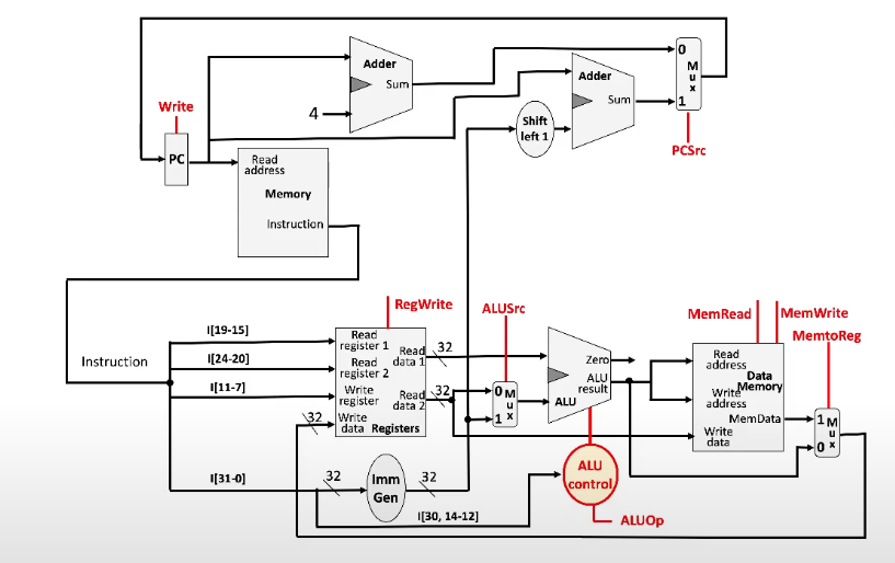
Complete Datapath
Steps for Each Instruction Type
All instructions start with fetch, decode because the instruction and registers always have to be read
R-Type (Arithmetic)
Fetch: load instruction from memory and increment PC
Read: read both registers from the register file
Setting of control lines is also computed in this step
Execute: ALU computes the data read from the register file. The opcode is used to tell the ALU which operation to execute
Write back: Write the ALU result back to the destination register
Load
Fetch and decode
Execute: ALU computes sum of value read from register file (address to load from) and sign-extended and bitshifted immediate
Memory: use result of the ALU as the address for the data memory
Write back: write data from memory unit into destination register
Branch-on-equal
Fetch, decode
Execute: ALU subtracts one register data value from the other. (Another ALU??) calculates the value of the target address by adding the sign-extended, bitshifted immediate to the PC
Write back: the zero status information from the ALU is used to determine which adder result gets stored in PC
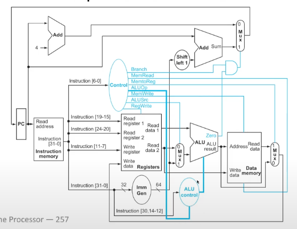
Datapath with Control
All of the control signals come from the control unit
Jump-and-Link instructions
Saves PC+4 in the \(R[rd]\) address (return address) and sets the PC to PC + offset (PC-relative jump)
Needs another adder (???)
V29 - Pipelining
Consider a task that uses a number of different resources. Instead of waiting each a task to be complete before starting the next one, we overlap the tasks so that each resource is being accessed by a different task, but at the same time
All modern processors execute in a pipelined fashion
Speedup
Speedup (finite amount of taskss): \(\text{Speedup} = \dfrac{\text{time to complete tasks}}{\text{time to complete pipelined tasks}}\)
Speedup (nonstop tasks): \(\text{Speedup} = \text{number of concurrent tasks on average}\)
Unbalanced pipelines (i.e. tasks that take different amounts of time) take longer
Speedup is increased through throughput; it does not affect the latency, i.e. the time that it takes to execute an instruction
RISC-V Pipeline
RISC-V instruction execution follows 5 stages
IF: Instruction Fetch
ID: instruction decode and register read
EX: Execute operation or calculate address
MEM: Access memory
WB: write back to register
Assume register read/write takes 100ps and other space take 200ps
Different formats take different times (load is the longest, branch is the shortest)
Longest takes 800ps, so as of now, each task takes \(\approx\) 800ps, stacked end to end
RISC-V can be pipelined by running each of these steps at the same time for different instructions
Pipelined version: each instruction takes 200ps, so on average, an instruction execution takes 200ps
ISA Design for Pipelining
All instructions are 32 bits → more uniform decoding for more balanced pipeline
Few and regular instruction formats → more overlap in the pipeline
Registers can be decoded and read in one step
Load/store addressing → address can be calculated in third stage, memory accessed in 4th stage
This is why we can't perform arithmetic operations directly from or to the memory
Hazards
Certain situations may prevent starting the next instruction in the next cycle
Structural Hazard: a resource the instruction needs is busy
Data Hazard: An instruction depends on data produced by a previous instruction
Control Hazard: control action (i.e. conditional) depends on the previous instruction
Structural Hazards
Processors don't actually have separate memory for instructions and data
Structural Hazard (precise): the data access of a load/store instruction and the instruction fetch need to use memory at the same time
Solution: processors have separate caches for "data memory" and "instruction memory"
Caches will be covered later
Data Hazards
An instruction depends on completion of data access by a previous instruction
// x1 may cause a data hazardadd x1, x2, x3sub x4, x1, x5
Solution 1: insert a bubble into the pipeline so that we have time for the data to become available
Bubble: a space in the pipeline that doesn't have an instruction
However, this decreases performance, so we would like to do something better
Forwarding (Bypassing)
Forwarding: using a result directly when it is computed instead of waiting for it to be stored in a register
This requires extra connections in the datapath
The output of the execution unit (i.e. ALU) is directly connected to the input of the execution unit
Load-use Data Hazard (Stall)
If data is being written into the memory and read from the memory directly in the next instruction, then we have no choice but to insert a bubble
Otherwise, the load would happen before the store due to the pipelining, since stores happen more than one stage after loads
Values cannot be sent backward in time
Code-scheduling to Avoid Stalls
The compiler knows how the pipeline works, so it can reorder code (!) to minimize load-use data hazards (and other hazards)
The compiler must understand the instruction dependency of the program to do this
[[V2A - Pipeline Control Hazards]]
V2A - Pipeline Control Hazards
Branches determine control flow, so fetching the next instruction depends on the branch outcome
This isn't always known yet, because the result of the branch (and thus the target instruction) may not have been determined by the pipeline yet
So, figuring out all the targets should be done as early in the pipeline as possible
This can be done by adding hardware, or by simply stalling on a branch
Speculative Execution
Instead of waiting (stalling) for the result, we start computing instructions as if we know the branch
If the prediction is right, we just keep executing, having saved time
If it's wrong, then we stall and recompute
This gets more and more efficient as pipelines get longer
Actual processors have between 14 and 20 stages in their pipelines
In RISC-V, this can be done by ignoring the branch (and moving onto the next instruction), since failed branches just move to the next one anyway
Instructions that turn out to be wrong are turned into NOPs (no-operation), which nullifies them
Instruction can be turned into a NOP by setting all the control lines to 0
Known as instruction/load squashing
Realistic Branch Prediction
Static branch prediction: Instead of just moving past the branch, the prediction should be based on typical branch behavior
E.g. any backwards branch is a loop, and most of the times, loops loop back many times before failing; why else would we write one? So, the backward branch is always taken
E.g any forward branch is a conditional. Generally, programmers put code they think will execute less often in the "else" block, so forward branches should not be taken
Dynamic branch prediction: the branch prediction depends on past behavior of either that branch or the branches in the program
Hardware measures (counts) branch behavior, i.e. they record the recent branch history
Stored in a table indexed by the address the branch branches to
We assume that future behavior will follow past behavior (general design principle in computer architecture)
Calculating the Branch Target
Even if a speculation is right, we still need to calculate the target address, which takes time and space in the pipeline
Solution: branch target buffer
Cache of target addresses addressed by the PC when the instruction is fetched
We can fetch the target immediately if we have used it before
Some architectures have a branch delay slot: the instruction directly after a branch is always executed
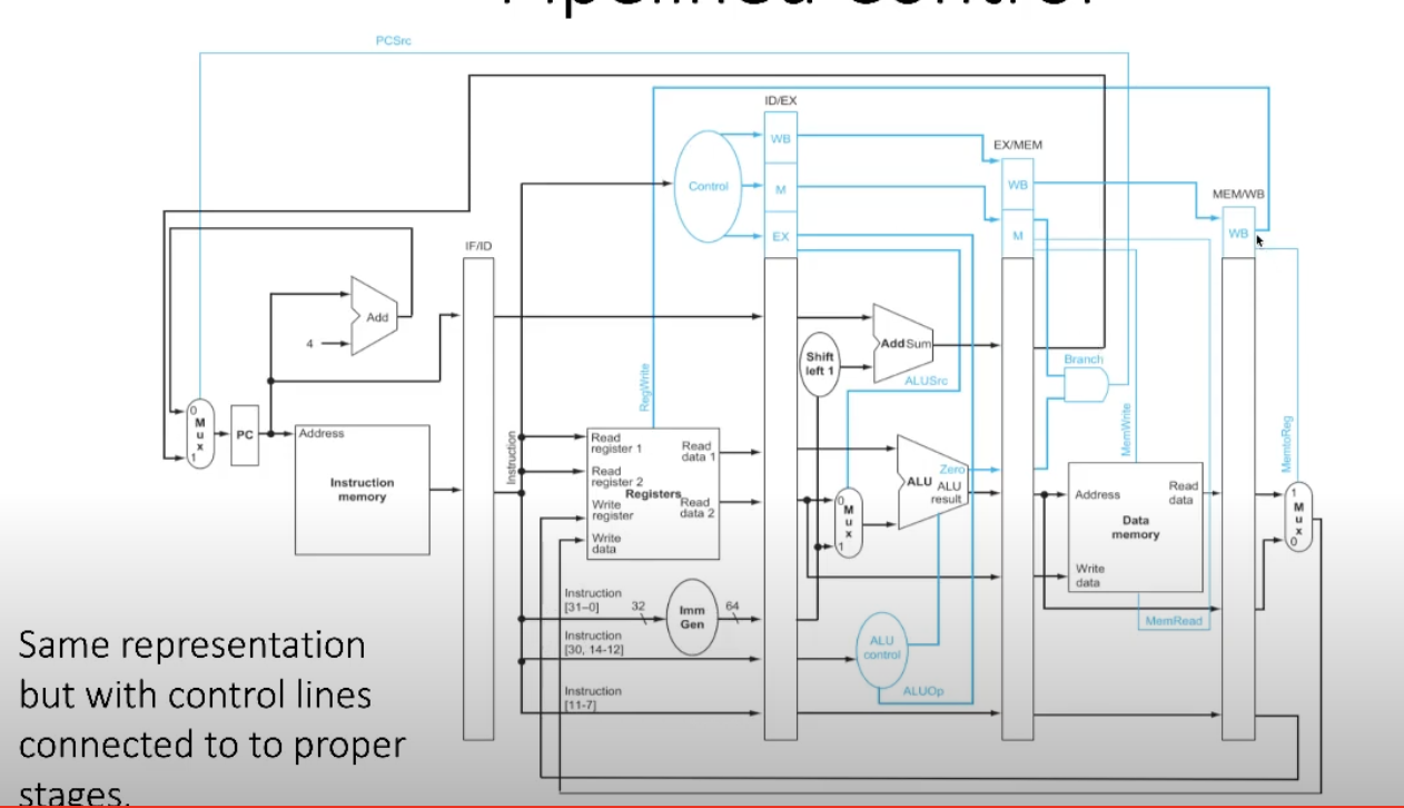
V2B - Pipelined Datapath
Our single-cycle datapath is not suitable for pipelining because all of the stages of execution are all done in a single circuit, at the same time
A pipelined execution requires a redesign of the datapath
Design Changes
For the initial datapath, the signals mostly flow from the left to the right, but there are some that flow backwards. Both of these are data hazards
Write back to registers
Next value of program counter
We need registers between stages to store the intermediate results between stages
These also need to store the control signals that will be used later
The bits that usually get fed back into the register file (for example) will get stored in the intermediate result register
Pipelined Control
Data Hazards in ALU Instructions
Possibility: we write to a register in one instruction, then read from that for another operation in the directly following instructions
In this case, the value accessed in the second instruction will be out of date
Forwarding
We can resolve these data hazards with forwarding: connecting components backwards (?) in the pipeline
V2D - Instruction-Level Parallelism
still make notes on this
Pipelining: executing multiple instructions in parallel
To increase ILP (Instruction-level parallelism):
Deeper pipeline (less work per stage → shorter clock cycle)
Wider pipeline (replicate pipeline stages → more instructions executed per clock cycle)
Multiple Issue
Static multiple issue: compiler groups instructions into "issue packets", which can be thought of as a really long instruction that contains many concurrent operations
Compile groups instructions to be issued together and packages them into "issue slots"
Dynamic multiple issue: CPU looks at the stream of instructions and chooses which instructions to issue each cycle
The compiler can reorder the instructions
However, the results must be committed back to the registers in order; this is required so that exceptions can work as expected
dynamically scheduled CPU
The way we have treated registers is a simplified concept; most instructions executed by the processor don't depend on the register at all; registers are names for values that propagate between instructions, not actual places that we store things (???)
register renaming: we can rename registers, I.e. change the location where registers are. This is done to eliminate read after write and write after write dependencies, I.e. lets multiple instructions be executed at the same if they use registers separately that won't affect each other
Only 32 registers because that's all the space available in the instruction to specify a register. We can have more registers not accessible by instructions, but still able to be used by the compiler
Why do dynamic scheduling?
Not all stalls can be predicted
Can't always schedule around branches
Different implementations of an ISA have different latencies and hazards
Speculation
When we guess what to do with an instruction
Start the operation as soon as possible, then check whether the guess was right
Do the common case fast, and do the rare case correct
I.e. it makes sense to spend a lot of time on the rare cases if the common cases are as fast as possible
If the speculation is wrong, roll back and do the correct thing.
If the common case really is common, immediately choosing it, then checking (and correcting if necessary) is cost-effective compared to always checking and always being correct
Example: speculation about whether a store instruction and a later load instruction store/load independent values or related values. We might speculate they are unrelated, then run both instructions at the same time since we don't think they affect each other
Speculation and Exceptions
If an exception occurs on a speculatively executed instruction
Static speculation: can add ISA support for deferring exceptions
Dynamic speculation: can buffer exceptions
V2F - Memory Hierarchy
So far, we have abstracted memory as an array
It turns out that memory is actually organized more complexly than a linear array
This complexity comes from the fact that different data storage technology has different expense and access time
Types of Memory
SRAM: static RAM: data remains stable as long as power is provided
Very quick to access, but extremely expensive per GB
DRAM: dynamic RAM: the data may disappear if the RAM is not refreshed
"Normal" access time (~100x) SRAM access time, normal price per GB
Storage drivers
Extremely slow access time but very cheap per GB
We want to emulate a system with the speed of SRAM, but that is more cost effective
Principles of Locality
Principle of locality: programs access a small portion of their address space at any time
Temporal locality: things accessed recently are likely to be accessed again soon
E.g. accesses done in loops
Spatial Locality: memory being accessed is usually close in the address space to other memory being accessed
E.g. accessing each element of an array in order
Taking Advantage of Locality
Everything (code and data) are stored in solid state drives
Recently accessed and nearby items are copied from disk to smaller DRAM (main memory)
The most recently accessed and nearby items are copied from DRAM into SRAM (cache memory) that is attached directly to the CPU
Its access time is very fast
Memory Hierarchy
Overview of memory hierarchy: there are various places to store things in memory. The most used locations are stored close to the CPU in very fast-access locations. The further away storage is from the CPU, the larger, slower, and cheaper it gets
Block: smallest unit of stored data (may be multiple words)
Hit: memory access that is satisfied by a higher level in memory
Miss: memory access is not satisfied
The hit/miss ratio is something that is important to consider for performance
Miss penalty: time taken to access non-cached memory
V30 - Cache Memory
Cache memory: level(s) of memory that are closer to the CPU than the storage
Identifying Blocks
Cache memory is measured in blocks; each block may be multiple words
Each block needs a unique identifier; \(2^k\) blocks means \(k\)-bit identifiers
Since each block may have multiple words, we need an offset to determine which word we are looking for
\(2^k\) words/block means \(k\)-bit offset
Cache Addressing
In order of LSB (right) to MSB (left):
First 2 bits: offset (when trying to access a specific word from each block)
Next 12 bits: cache block index
Rest of the address: tag, which is stored before the block
Identifies which address in memory the block came from
We only store as many bits as we can fit
Note that since there are \(2^{32}\) memory locations, multiple (many) memory locations map to the same place in the cache
However, we still need to know if the content of the block is valid (i.e. was the address we are looking for stored there, or a different one that maps to the same place?)
There is a "valid bit" that is 1 if the cache is valid and 0 otherwise
Associativity
We want a given memory address to be able to map to more than one block into a cache
Use case: if a memory location is used over and over, we have to rewrite to the cache each time, which defeats the purpose
Solution: we group blocks into a set
Each block still has a valid bit and a tag
Each set gets a valid id, but we need less of these than for the blocks since there are multiple blocks per set
Now, when matching a tag, we have to check each tag in the set to see if it matches, which takes more time
New notation: 0xFF00_0 for 17 bits: first four digits are hexadecimal, then the last is binary
When placing new blocks in the cache:
We must decide which block to remove
Best policy: we remove the block that has been used the least recently (application of temporal locality)
To implement this, we add one more bit to the cache design to indicate the least recently used bit (LRU bit)
\(n\) blocks per set: \(n\)-way associative cache
Increasing associativity decreases the miss rate, but returns are diminishing
Set-associative cache diagram
V31 - Block Size and Associativity
We can figure out how many bits we need per block (offset bits) and how many sets there are in the cache (index bits)
more calculations here, but the follow from the definitions
LRU for Higher Associativity
The higher the associativity, the more bits we need to keep track of the LRU location (e.g. \(2^n\) associative → \(n\) LRU bits)
This gets expensive quickly, so sometimes it makes more sense not to precisely track the LRU bits
2-way is simple, 4-way is manageable, but more than that is not worth tracking precisely
Picking randomly (which can be done with hardware, thanks IBM!) is generally pretty good because it avoids worse-case picks (statistically)
Alternative: Not Most Recently Utilized
Tree-based algorithm for approximating LRU
Each node in the tree is one bit, which indicates which side (left or right) the LRU is
When a block (leaf) is accessed, the node bits are flipped recursively upwards if they point towards that block
For an \(n\)-way set associative cache, requires \(n\) bits
Replacement Policy
Direct mapped: no choice but to replace what's in the cache if two things are saved to the same address
Set associative
Prefers to replace an invalid entry, if there is one
Otherwise, we must choose somehow (generally LRU or LRU approx, maybe random)
Finding the Block from an Address
Finding the block an address points to in an \(n\)-way associative cache: \(\lfloor \frac{\text{address}}{\text{bytes per block}} \rfloor \mod \text{\# of blocks}\)
I.e. if an address is "larger" than the cache, it just wraps back around to the start, modulo-style
Large Blocks
Larger blocks reduce miss rate, due to spatial locality
However, larger blocks → less blocks → more competition for a particular block → higher miss rate
Specifically, pollution (bringing things into the cache that don't get used again) is more of an issue
Also, larger block → larger miss penalty
Larger Cache
Why not just make the cache larger?
The size of the cache is limited by the physical distance between blocks in the cache
The distance to the furthest cache block puts a lower bound on cache access time
V32 - Write Strategy
Strategy for Hits
Write-back Policy
When the processor is trying to do a store, and the location to write to is in the cache
In this case, the write is only written to the cache!
However, the corresponding block in memory is now out of date (stale)
We can add a dirty bit to our cache storage that gets changed when we take it from memory (this helps us keep track of changes, since now, the act of storing this in the cache changes it)
Then, when the block is (presumably) eventually removed from the cache, we right its new value back into memory
Write-through Policy
Instead of just writing to the cache (like write-back), any change to the block gets written to both the cache and the memory
Thus, the memory and cache are always synchronized
Strategy for Misses
Write-allocate Policy
Equivalent to write-back policy
Processor fetches entire block from memory, makes space for it in the cache, and writes it into the cache
The line is how dirty, which is encoded by the dirty bit
Write-around Policy
Equivalent to write-through
The new values is only written to the memory
What is the point… the cache doesn't get used…
Write Buffer
No matter the policy, writing to memory takes a very long time, and may halt other instructions (i.e. reads)
We can add another layer (a write buffer) to the memory hierarchy to help with this
It is small and close to the cache, so it can be read from and written to quickly
At some point, there will be enough resources to transfer the contents of the write buffer to memory. Then, the write buffer is cleared
With every read, we must how check if what we are looking for is in the write buffer or memory
We have to search every entry in the write buffer for this. Yikes!
L3 and L4 caches are present in some systems, but main memory usually comes after L2
Interactions with Advanced CPUs
Out-of-order CPUs can execute instructions during a cache miss
Pending store stays in a load/store unit
Dependant instructions accumulate in reservation stations while independent instructions continue
Performance analysis is much harder to work out directly; we rely on actual simulations to measure performance
Interaction with software
Code should be written with locality in mind, since it will (in theory) run faster on hardware
Compilers also optimize for memory access
V36 - Virtual Memory
Lies!! When you access data from memory (as the processor), the address the processor generates is not the same as the actual address the data is stored at
Why Lie?
Data protection: if all programs can access all the memory, then data may leak (accident) or be spied on (on purpose)
Providing the illusion of larger memory
This made more sense when machines had very limited memory (i.e. punch-card days)
Overview
We have a cache, main memory, and a disk
Cache → memory is like memory → disk; the disk is much larger but much slower
We use the same locality principles
We divide the data in the main memory into pages (often 4Kb)
Each page consists of a number of cache blocks
Pages are stored on the disk
The main memory is used as a cache for the content of the disk
This system is called virtual memory
VM is managed by both hardware and software (because of the large sizes of data involved), unlike the memory cache, which is all hardware
Virtual Address Space
Each program has a private virtual address space, all of which map to the physical memory address space
Pages in the virtual space correspond to frames in the physical space; maps exist between individual pages and frames
Hardware and OS operate this system
Data may be shared between programs through the frames, but this requires operating system permission
The "cache miss" for virtual memory is called a page fault
Page faults are incredibly slow, so we really want to minimize them
Very smart replacement algorithms (OS topic)
Non-associative mapping
Address Translation
Some virtual addresses map to physical addresses; some map to the disk (if there is a page fault?)
Pages, like blocks, have page numbers and page offsets
The page offset isn't changed when addresses are translated
The page number is translated into a physical frame/page number
Address Translation in RISC-V
We store a bunch of indexes in the virtual address that point to the root table; looking them up, then looking the result up in the table, etc, leads to the physical address
SATP: Supervisor Address Translation and Protection register
Contains physical page number, address space identifier, and mode (write any values, read legal values)
missing
Writes
Disk writes take millions of cycles → we use write-back with a dirty bit in the PTE
Translation Lookaside Buffer
TLB caches the virtual address → physical address process, since by the principles of locality, we probably access the same addresses often
A TLB miss may either mean a page is present (but not indexed in the TLB), or not present at all
So, a miss raises an exception that copies the PTE from memory to the TLB, then restarts the instruction
If the page is not present, a page fault will occur and be dealt with normally
Page Fault Handler
Use faulting VA to find PTE
Locate the page on the disk
Choose the page to replace (if dirty, write to disk first)
Read page into memory and update the page table
Return to the normal process
Memory Protection
Different tasks can share parts of the virtual address space, but we need to protect against errant access
Hardware has support for OS protection
Privileged supervisor mode (kernel mode)
Privileged instructions
Page tables and other state information only accessible in supervisor mode
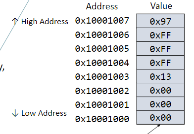
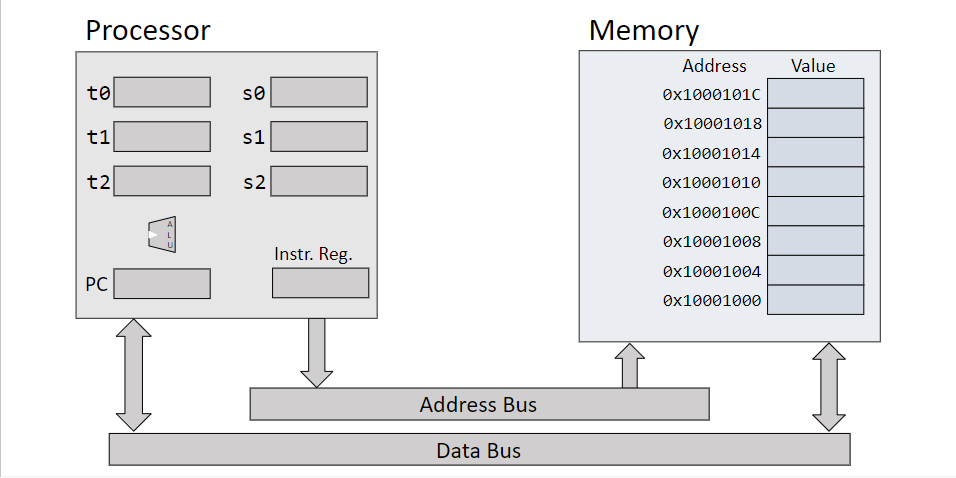
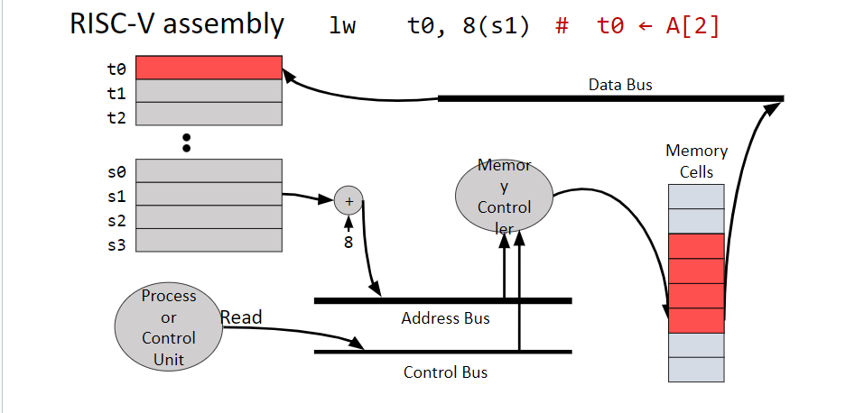
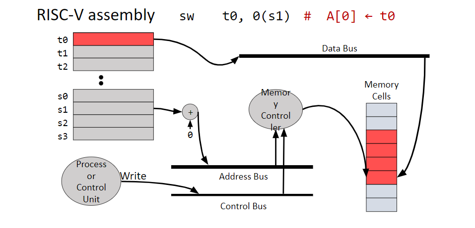
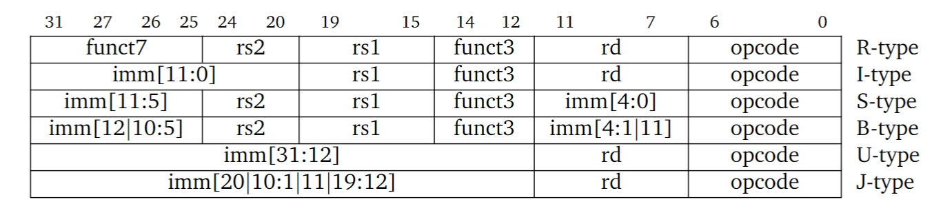
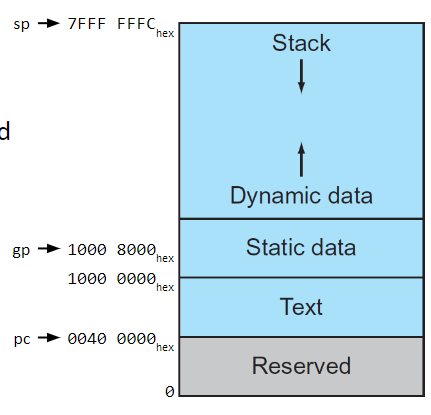
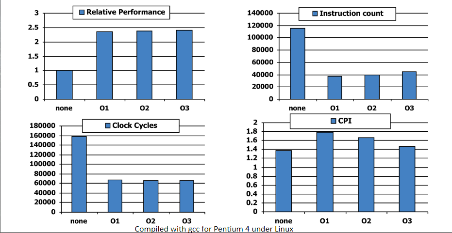
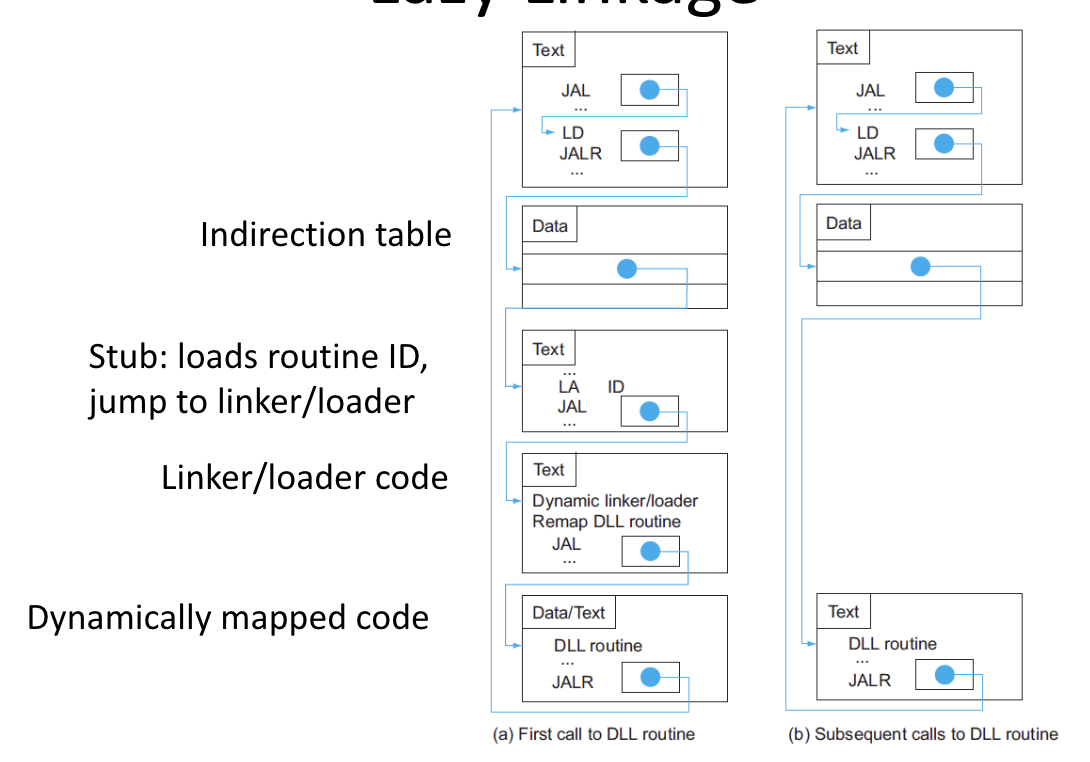
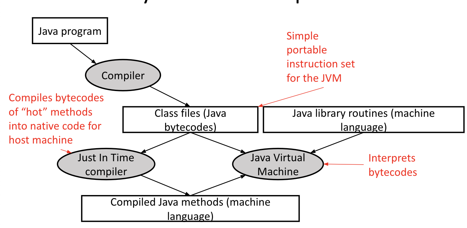
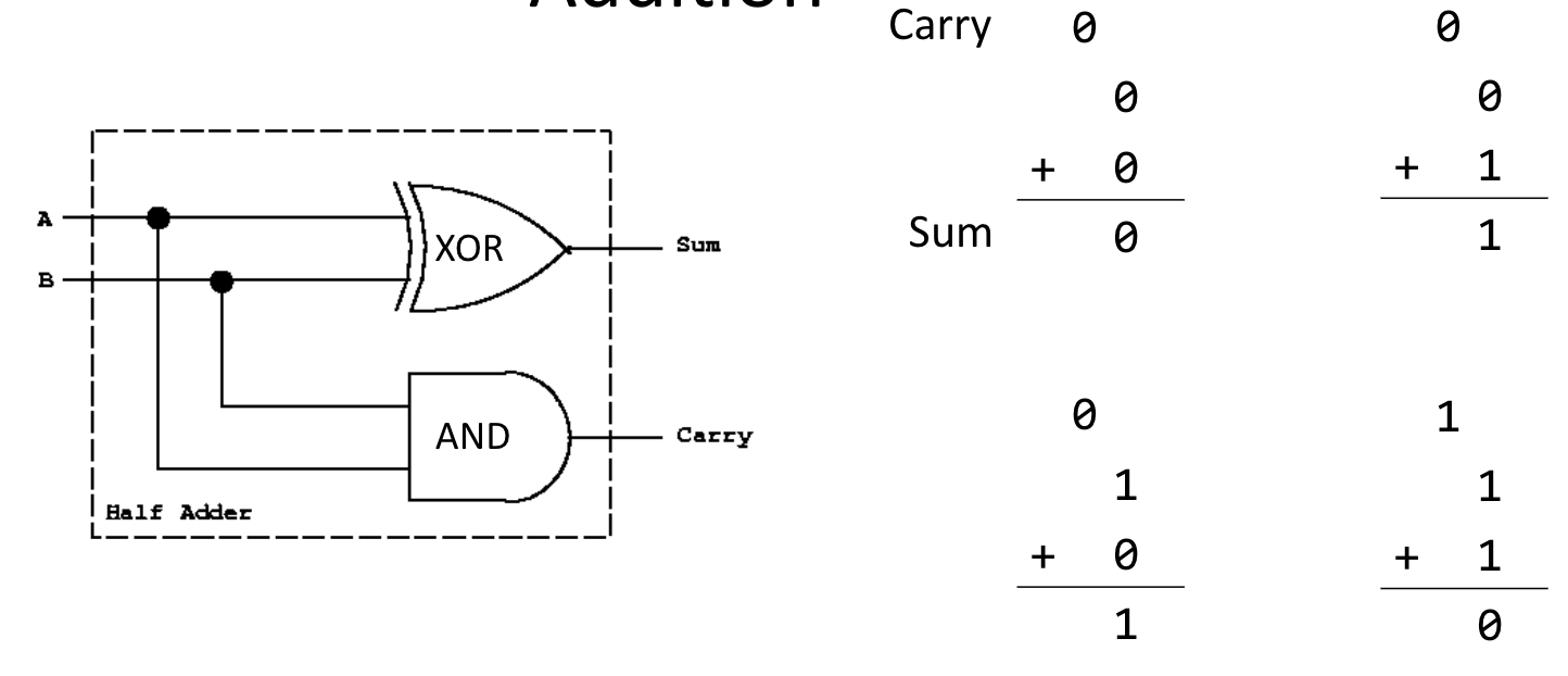
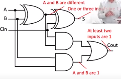
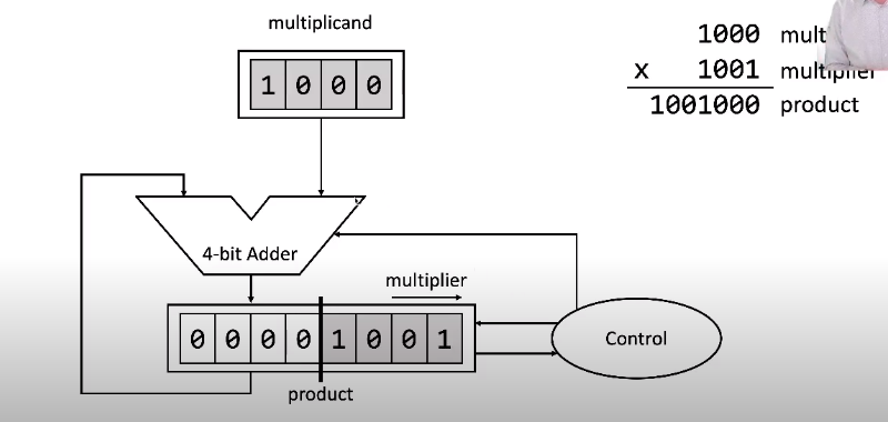
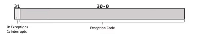
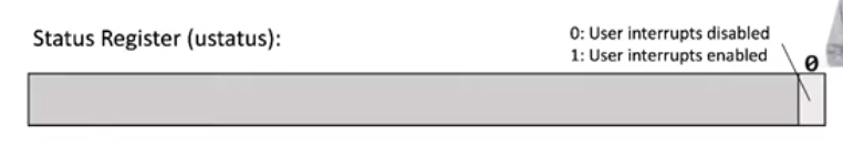
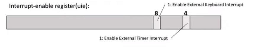
 - Parallel bus: multiple data lines (wires)
- Busses are either synchronous (and use a clock signal like a processor) or asynchronous (use some sort of handshake)
- Parallel bus: multiple data lines (wires)
- Busses are either synchronous (and use a clock signal like a processor) or asynchronous (use some sort of handshake)
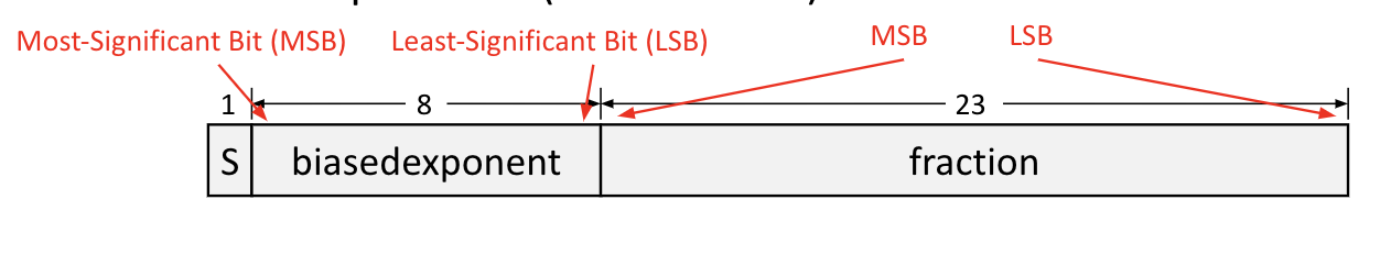
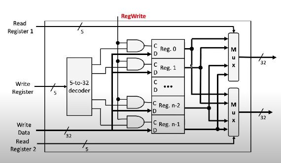
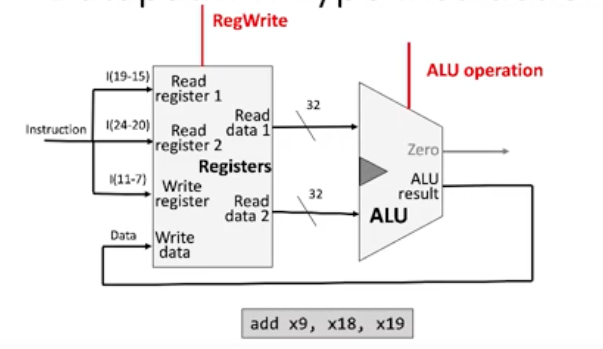
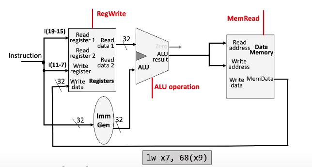
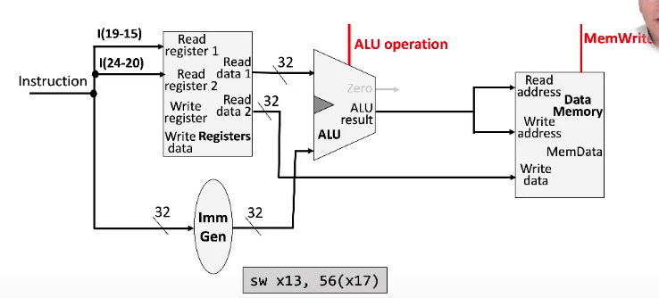 - Don't have to write into the register file, since store instructions don't change the value of any registers
## Combining Arithmetic and Load/Store Designs
- If we combine these into one circuit, there are two possible inputs for the ALU data
- We use a mux to determine which signal gets used
- ALU mux control signal: `ALUSrc`
- The same thing happens for the signal that goes into the register file's write data (memData vs. ALU result)
- Register file mux control signal: `MemToReg`
- Don't have to write into the register file, since store instructions don't change the value of any registers
## Combining Arithmetic and Load/Store Designs
- If we combine these into one circuit, there are two possible inputs for the ALU data
- We use a mux to determine which signal gets used
- ALU mux control signal: `ALUSrc`
- The same thing happens for the signal that goes into the register file's write data (memData vs. ALU result)
- Register file mux control signal: `MemToReg`